
Abstract
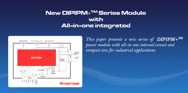
This paper presents a new series of DIPIPM+TM power module with all-in-one internal circuit and compact size for industrial applications. To achieve lower power losses, the 7th generation IGBT chip is employed into the DIPIPM+. With highly integrated and compact size, it can be used easier in the industrial field, such as inverter, servo, motor driver, etc.
Synopsis
1. Introducing
DIPIPM product family, for inverter application, has been more and more popular in the industrial market. The characteristics of high integrated, high power density, compact size, easy assembly are advantages which be preferred by engineers.
Now, combined with rectifier, inverter unit and brake unit have been integrated into a single package, DIPIPM+ makes it much easier to utilize then shortening the period from R&D to mass production.
And, with the newest 7th generation IGBT technology has been employed, DIPIPM+ has
lower power losses.
2. Description of the DIPIPM+TM
2.1 Chip Technology
DIPIPM+ has employed the 7th generation IGBT chip with CSTBTTM technology. The new chip uses the new process to achieve power losses reducing in which conducting and switching simultaneously; thinner wafer for lower VCE (sat), and fined cell pith for lower Eoff.
To compare with 6th generation IGBT chip, the characteristics of VCE (sat) and Eoff has reduced
for about 7% (Figure 1) and 25% (Figure 2) respectively. Therefore, high current density can be realized in a compact package.
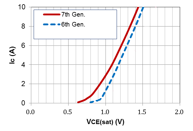
Figure 1 VCE (sat) comparison – 6th vs. 7th
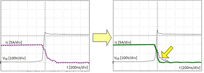
Figure 2 IGBT chip turn-off loss comparison - 6th vs. 7th
2.2 High integration
To designers, ones prefer that, the power devices which for structuring a three-phase inverter are integrated into a single package (Fig.3). By high integration, the works for circuit design and module assembly become simple and easy. Then, CIB (Converter-Inverter-Brake) and PIM module came into being as market demand. Further, adds on with gate drive and protection circuit, DIPIPM+ is a convenient choice for designers.
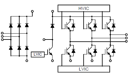
Figure 3 Illustration for internal connection of DIPIPM+
2.3 Optimized control part
2.3.1 Block diagram of Inverter unit
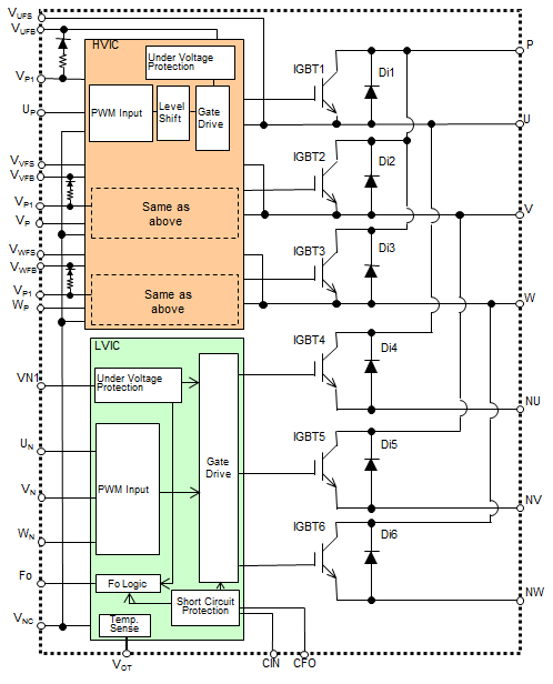
Figure 4 Block Diagram of Inverter unit
According to the block diagram, control part includes HVIC and LVIC in which to adapt up- arm and low-arm respectively. Refer to the function block; PWM signal transmitting circuit, under voltage protection, short circuit protection and fault signal output circuit are integrated. And more, analog temperature voltage output (VOT) function is integrated so that the temperature of module can be monitored in real time.
2.3.2 Internal bootstrap diode and current limiting resistor
In purpose that it can be used with single +15V power for control part of DIPIPM+, HVIC is employed. Corresponding that, the bootstrap circuit is needed for supporting to drive up-arm. Benefited by utilizing of new processes, power consumption of HVIC is lower so that the bootstrap diode and the current limiting resistor can be integrated (Figure 4).
2.3.3 Temperature-analog output (VOT) Function
Based on the Statistic Analysis of failure data, OT is a main cause of power chip destruction; thus, it should be avoided when the module is operating under abnormal conditions. Therefore, the temperature of power chip or case of module should be sensed.
In practical, the NTC resistor is installed into the power module as the sensor to monitor the related temperature in purpose. DIPIPM+ has the similar design; the thermal sensor is embedded on the LVIC to monitor the case temperature (Figure 5).
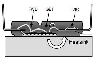
Figure 5 Illustration for the theory of thermal detecting
However, the thermal sensors of which be used in the power modules are the component with non-linear characteristics versus temperature. It may cost some resource of software on logarithmic computing or table look-up so as to get the corresponding value when it would be used. To simplify this procedure, the LVIC of DIPIPM+ has built in a compensation circuit for translating the temperature on LVIC to voltage which with linear characteristic (Figure 6). The voltage can be utilized by MCU easily with analog-digital conversion program. Meanwhile, programmer can adjust the control algorithm according to the real time temperature.
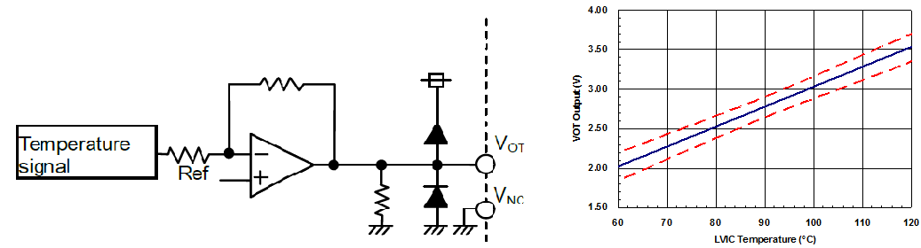
Figure 6 Internal circuit for VOT Function & output voltage characteristics
3. Power losses simulation
To describe the performance of DIPIPM+, the power losses simulation has been done;
and the comparison between DIPIPM+ and large type DIPIPM has been done also (Figure 7).
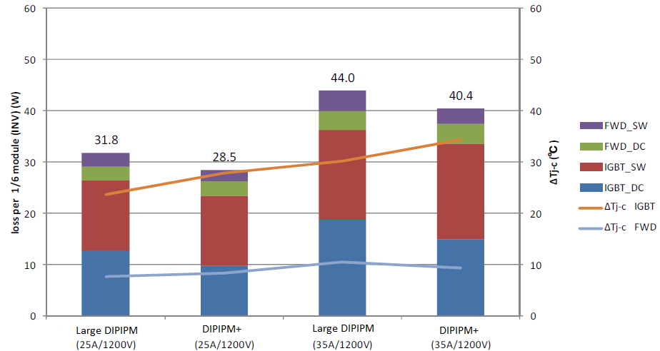
Figure 7 Power Losses comparison – Large DIPIPM vs. DIPIPM+
According to the figure 7 shown, DIPIPM+ has about 10% reduction of power losses than the large DIPIPM.
4. PCB Layout example
Another advantage for DIPIPM+ is the reasonable pin assignment. It is easy to divide the pins into power pin portion and signal pin portion (Figure 8).
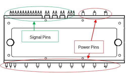
Figure 8 Pin assignment
So, it seems to design the PCB layout easier (Figure 9).
It’s easy to find that, the power terminals such as input terminal, output terminal and brake resistor terminal are all set onto the same side without cross wiring. And, low count of peripheral component makes the design simple, more, PCB size is saved.
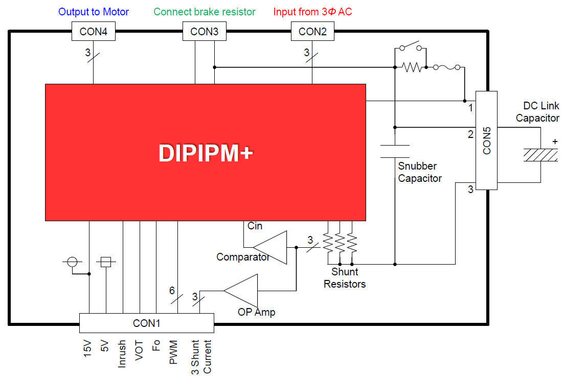
Figure 9 PCB layout example
5. Conclusion
The new DIPIPM+ series module shows more advantages; high integration, lower power losses and lower count of peripheral component make the application simple and compact. However, high integration and power density mean the heating is concentrated, so, it is needed to be careful on cooling system design. And, absence of short circuit protection in HVIC is a disadvantage which may cause failure by large current which in case of the load would be shorted to N point. Furthermore, it’s an unknown risk for the situation in which fault info of HVIC cannot be passed out.
References
[1]. Eric R. Motto, “Standard packages and features for DIPIPMTM in small motor driver applications”, ECCE 2013.
[2]. L. Xiaoguang, M. Shiramizu, A, Yamamoto, C. Tadokoro, T, Nakano “BSD embedded new series super mini DIPIPMTM Ver.4” 2010 PCIM China.